Actuator Disk Test Cases
WIPP Test Case
This test case was part of the Workshop for Integrated Propeller Prediction (WIPP) and results are documented in the paper entitled: "Comparison of Propeller-Wing Interaction Simulation using Different Levels of Fidelity", Z. Yang, A. Kirby and D. Mavriplis, AIAA paper 2022-1678, DOI: 10.2514/6.2022-1678, available at: https://scientific-sims.com/cfdlab/Dimitri_Mavriplis/HOME/assets/papers/6.2022-1678.pdf
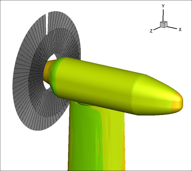
The test case is described in detail in the paper. The figure below illustrates the general configuration. This figure was constructed using the NSU3D post_proc facility to generate the surface geometry of the wing/nacelle, and the actuator disk actdisk_loads.ncycles.dat file to render the actuator disk location and momentum source grid. The last figure illustrates the fact that the actuator disk momentum sources are overset in the CFD mesh and do not align with any specific mesh surfaces. Note that all disk source point locations are plotted on the disk, although a gap appears in the figure along the last source radial line in the list, which is intentional.
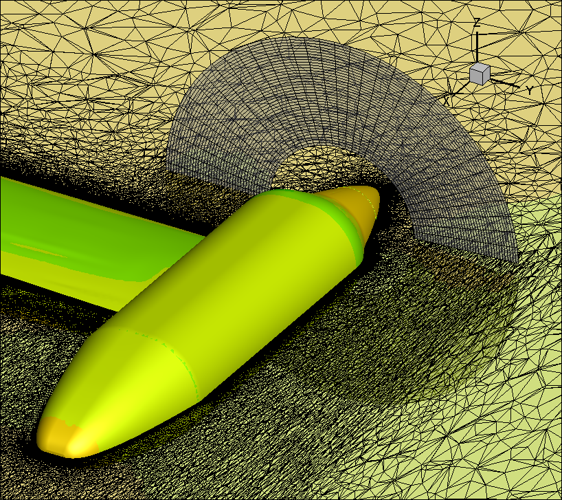
The flow conditions are Mach=0.08, Re=567,801/ft. Here we focus on the Incidence = 0 deg case, although a full range of flow incidences was run in the paper to generate a drag polar.
Five test cases are shown to illustrate the application of the different actuator disk loading types and functions:
- Case 1: Assumed load distribution (loadtype=1,2) :
- For a given thrust coefficient C_T and power coefficient C_Q, the loading can be obtained by assuming a prescribed disk load distribution, such as a linear distribution in the radial direction.
- Case 2: Prescribed loading (loadtype=4) :
- The loading is given by other methods or by test data, such as that supplied by the workshop organizers.
- Case 3: Blade-element theory loading (loadtype=3) :
- If the blade geometry is known, the blade-element method can be applied to compute the loading for the actuator disk. The flow velocities combined with the blade geometry and rotational speed are used to obtain the effective local angle of attack. With the local Mach number and the effective angle of attack, the lift/drag coefficients can be obtained from sectional airfoil CL/CD-AoA-Ma tables or charts and used to prescribe the appropriate momentum source terms. This method predicts rotor thrust and torque values that depend on the blade shape, speed of rotation, and the incoming computed flow field, providing two-way feedback between the flowfield and rotor.
- Case 4: Blade-element theory loading (loadtype=3) with trim control:
- This case is similar to Case 3, but now includes trim control, where the collective blade pitch angle is adjusted throughout the simulation to match a prescribed thrust value.
- Case 5: Example of dual rotor system using blade element loading
CASE 1: Assumed Load Distribution Case (loadtype=1,2)
This case uses a linear loading profile by specifying the parameter loadtype=2 in the actdisk_system namelist of the input.actdisk file. Listing the relevant parameters in the input file under each namelist we have:
actdisk_info :
For this case, with a single rotor, there is one system (nsystem=1) and a total of one rotor (nrotor=1).
- nsystem=1 indicates that there is one system of rotors.
- nrotor=1 indicates that there is a single rotor for all systems.
- nblade=1 denotes a single blade type used for this case.
- nairfoil=0 indicates that no airfoils are required for this case, since this a prescribed load case.
- show_system=false is the defaut and could be omitted.
- show_rotor=true will cause rotor loads to be written to std-out at each actuator disk evaluation (each flow cycle in this case).
- force_output_unit = "lb": This is also the default value because the ref_length_unit parameter specifies inches. However it is included here for completeness.
- moment_output_unit="lb*ft": The same applied to this setting.
actdisk_system :
For this case, since there is only one system and one rotor, the list of rotors in the system (rotor_list) does not need to be specified.
- center_of_gravity lists the coordinates for force/moment integration, which is the same in this case as the hub center or center of rotation of the single rotor.
- target_value=40 specifies a total thrust of 40 lbs as determined by the specified condition for this case. This scales the magnitude of the loading distribution to match the required thrust level.
- init_collective=0.0 is the default. However, note that a specified torque/power can be matched by adjusting this parameter by modifying the direction of the load vector (at constant specified thrust level).
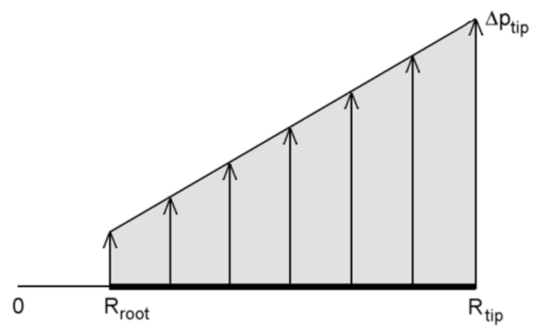
- loadtype=2 specifies a radial linear distribution of the load as shown in the figure below.
actdisk_rotor :
This namelist only appears once in this input file, since there is a single rotor for this case, as sepcified by nrotor=1 in actdisk_info
- rotation_rate specifies the speed of rotation of the rotor. Although this input is not needed to compute the loads in a prescribed load case, it is used in the nondimensionalization of the thrust and torque coefficients.
- hub_coord corresponds to the coordinates of the hub origin or the center of rotation of the rotor.
- shaft_axis designates the axis of rotation, which in this case is in the x-direction, pointing forward (-ve x) as in the figures above.
- zero_azimuth_axis designates an axis normal to the shaft axis which is used for specifying the cyclic pitching parameters. Technically this is not needed for fixed blade pitch rotors in the absence of cyclic pitching, although it is included for completeness.
- blade_count=1 The number of blades for the prescribed loading cases is irrelevant. However, because a blade shape must be included as part of the definition in these cases, a blade count of 1 is used here, and the parameter nblade in actdisk_info was set to 1.
- nradial=400 Specifies 400 momentum source points in the radial direction of the actuator disk.
- nnormal=720 Specifies 720 momentum source points in the azimuthal direction of the actuator disk. Note that this is a disk with no thickness, since the axis(1:2) parameter is not specified. These source settings produce 400x720 = 288,000 sources in the disk. This is relatively high resolution. The figures above illustrate a disk with a reduced numver of 40x72=2,880 sources for clarity.
actdisk_blade :
This namelist only appears once in this input file, since there is a single blade type for this case, as sepcified by nblade=1 in actdisk_info
- chord_sta(1:2): Here only two chord stations are required. The root and tip stations define the extent of the actuator disk as shown in the figures above. The chord values are irrelevant for loadtype=1,2 and can be omitted.
- twist: Note that for prescribed load cases, only the blade twist and init_collective are relevant. This is because the blade shape is used to specify the direction of the local load vector, which is assumed to act normal to the local blade chord. While the thrust level is specified in the input, the torque and resulting swirl wake velocity result from the non-aligned component of the overall load with the hub axis along the rotor blade. If the twist values are not specified and init_collective=0.0, no torque/swirl will be produced. Blade twist can be used to specify the local contributions to the torque/swirl, and the overall magnitude can be specified by adjusting init_collective.
actdisk_blade :
Since nairfoil=0 in actdisk_info, no parameters under this namelist need to be specified and this section can be omitted.
Listing 1: input.actdisk input file for Case 1
1  ! WIPP Prescribed Linear Loading Test Case
2
3  ! Initialization namelist for sea level standard atmosphere
4  &actdisk_info
5    nsystem            = 1,
6    nrotor             = 1,
7    nblade             = 1,
8    nairfoil           = 0,
9    ref_length         = 1.0,       !L_physical / L_grid
10   ref_length_unit    = "in"       !Default is in. ft or in triggers lb below. Otherwise is SI.
11   show_system        = .false.,
12   show_rotor         = .true.,
13   force_output_unit  = "lb",     !These should be the defaults because ref_length_unit is inches
14   moment_output_unit = "lb*ft"   !But specify for completeness
15 /
16
17 &actdisk_system
18   system_name            = "WIPP System"
19   center_of_gravity(1:3) = -1.14663, 67.45, 0.0,
20   cg_unit                = "in",
21   init_collective        =  0.,    !Can modify to match Cq (default=0)
22   target_value(1)        =  40,
23   target_unit(1)         = "lb",
24   loadtype               =  2      !Loadtype for linear load profile (set=1 for constant profile)
25 /
26
27 &actdisk_rotor
28   rotor_name             = "WIPP Rotor"
29   rotation_rate          = 5905.0,              ! Counter-clockwise (Only used for thrust/mom coefficients)
30   rotation_unit          = "rpm",
31   hub_coord(1:3)         =-1.14663, 67.45, 0.0,
32   hub_unit               = "in",
33   shaft_axis(1:3)        =-1.0,     0.0,     0.0,
34   zero_azimuth_axis(1:3) = 0.0,     1.0,     0.0,
35   blade_count            = 1,                   ! Set= 1 for prescribed loading
36   nradial                = 400,
37   nnormal                = 720,
38 /
39
40 &actdisk_blade
41  station_unit      = "in",        !NOTE: Force is perpendicular to blade orientation (including collective)
42  chord_sta(1:2)    =  3.24,  8.1,
43  twist_sta(1:9)    = 3.0780, 3.9998, 4.6000, 5.2002, 5.7996, 6.3998, 7.0000, 7.4002, 8.0004,  !Optional: Defaults are = 0.0 producing Cq=0
44  twist(1:9)        = 33.298, 30.420, 29.481, 29.710, 28.087, 26.637, 21.219, 18.688, 17.499,  !Optional: Defaults are = 0.0 producing Cq=0
45  twist_unit        = "deg",
46 /
CASE 2: Prescribed loading (loadtype=4)
This case uses a prescribed load profile by specifying the parameter loadtype=4 in the actdisk_system namelist of the input.actdisk file. The load profile was obtained experimentally in the WIPP workshop and is reproduced in Figure 3 of the AIAA paper cited above. These loads were supplied as normal and tangential load values with respect to the actuator disk plane along the radial direction. These values were used to construct a load vector distribution along the radial direction. A blade twist was then constructed in order to match the load vector direction at each radial station with the blade chord normal direction, and the total loads were applied at each station in the direction normal to the blade chord. Many of the input parameters are similar between this case and the previous case and thus only the main differences are highlighted here.
actdisk_info:
These parameters are identical to those in the previous case.
actdisk_system:
- loadtype=4 This specifies the use of prescribed loads for this case.
Other parameters, such as target_value should not be used, since the resulting thrust level is a byproduct of the specified loads. Also, init_collective=0.0 is the default and should be assumed. If the collective is changed, the load vector will rotate with the blade pitch and no longer correspond to the original prescribed values.
actdisk_rotor:
All the parameters in the previous case have the same values in this case. In addition, the rotor loading must be specified here. This is done using the following parameters:
- loading_sta: These are the stations along the radial direction at which the loads are specified.
- loading: These are the magnitude of the load vector at the specified stations along the radial direction. In this case the loads are specified in pounds per square foot (psf).
actdisk_blade:
A single blade type is used and all parameters are identical to those used in the previous case.
actdisk_airfoil:
Since nairfoil=0 in actdisk_info, no parameters under this namelist need to be specified and this section can be omitted.
Listing 2: input.actdisk input file for Case 2
1  ! WIPP Prescribed Loading Test Case
2
3  ! Initialization namelist for sea level standard atmosphere
4  &actdisk_info
5    nsystem            = 1,
6    nrotor             = 1,
7    nblade             = 1,
8    nairfoil           = 0,
9    ref_length         = 1.0,  ! L_physical / L_grid
10   ref_length_unit    = "in"
11   show_system        = .false.
12   show_rotor         = .true.,
13   force_output_unit  = "lb",         !These should be the defaults because ref_length_unit is inches
14   moment_output_unit = "lb*ft"       !But specify for completeness
15 /
16
17 &actdisk_system
18   system_name             = "WIPP SYSTEM",
19   center_of_gravity(1:3) = -1.14663, 67.45, 0.0,
20   cg_unit                = "in",
21   loadtype               = 4                    ! loading type for Prescribed Loads
22 /
23
24 &actdisk_rotor
25   rotor_name              = "WIPP ROTOR",
26   rotation_rate          = 5905.0,              ! Counter-clockwise  (Only used for thrust/mom coefficients)
27   rotation_unit          = "rpm",
28   hub_coord(1:3)         = -1.14663, 67.45, 0.0,
29   hub_unit               = "in",
30   shaft_axis(1:3)        = -1.0,     0.0,     0.0,
31   zero_azimuth_axis(1:3) =  0.0,     1.0,     0.0,
32   blade_count            =  1,                   !Set=1 for prescribed load
33   nradial                =  400,
34   nnormal                =  720,
35   station_unit           = "in"
36   loading_unit           = "psf"
37   loading_sta            = 3.0780, 3.9998, 4.6000, 5.2002, 5.7996, 6.3998, 7.0000, 7.4002, 8.0004,
38   loading                = 9.408, 15.085, 18.791, 20.289, 20.427, 20.486, 19.634, 19.058, 19.066,
39 /
40
41 &actdisk_blade
42   station_unit      = "in",        !NOTE: Force is perpendicular to blade orientation (including collective)
43   chord_sta(1:2)    =  3.24,  8.1,
44   twist_sta(1:9)    = 3.0780, 3.9998, 4.6000, 5.2002, 5.7996, 6.3998, 7.0000, 7.4002, 8.0004,
45   twist(1:9)        = 33.298, 30.420, 29.481, 29.710, 28.087, 26.637, 21.219, 18.688, 17.499,
46   twist_unit        = "deg",
47 /
CASE 3: Blade-element theory loading (loadtype=3)
Setting loadtype=3 in the actdisk_system namelist specifies the blade element method, where the local loading is deterimed from the local flow conditions and a set of airfoil lookup tables. Note that this method produces actuator disk loading that is dependent on the local flow conditions, whereas the other methods produce constant loading distributions that are independent of changes in the flow field. This setting requires prescribing the blade properties under the actdisk_blade namelist, along with specifying the airfoil table files under the actdisk_airfoil namelist.
- actdisk_info:
For this case, with a single rotor, there is one system (nsystem=1) and a total of one rotor (nrotor=1).
- nsystem=1 indicates that there is one system of rotors.
- nrotor=1 indicates that there is a single rotor for all systems.
- nblade=1 denotes a single blade type used for this case.
- nairfoil=7 indicates that 7 different airfoils are required to define the blade shape for this case. This requires 7 airfoil files under the actdisk_aifoil namelist.
- show_rotor=true will cause rotor loads to be written to std-out at each actuator disk evaluation (each flow cycle in this case).
- force_output_unit = "lb": This is also the default value because the ref_length_unit parameter specifies inches. However it is included here for completeness.
- moment_output_unit="lb*ft": The same applied to this setting.
actdisk_system:
For this case, since there is only one system and one rotor, the list of rotors in the system (rotor_list) does not need to be specified.
- center_of_gravity lists the coordinates for force/moment integration, which is the same in this case as the hub center or center of rotation of the single rotor.
- init_collective=28.432 sets the collective pitch angle for the blades of the rotor. This value is added to the twist values in the blade definition, completing the definition of the blade positions for the rotor.
- loadtype=3 specifies the blade-element method.
actdisk_rotor:
- This namelist only appears once in this input file, since there is a single rotor for this case, as sepcified by nrotor=1 in actdisk_info
- rotation_rate specifies the speed of rotation of the rotor. As opposed to the previous (prescribed load) cases, the rotation rate is required to determine the incoming velocities at the blade stations that are used to compute the local blade loads.
- hub_coord corresponds to the coordinates of the hub origin or the center of rotation of the rotor.
- shaft_axis designates the axis of rotation, which in this case is in the x-direction, pointing forward (-ve x) as in the figures above.
- zero_azimuth_axis designates an axis normal to the shaft axis which is used for specifying the cyclic pitching parameters. Technically this is not needed for fixed blade pitch rotors in the absence of cyclic pitching, although it is included for completeness.
- blade_count=4 This specifies a four-bladed rotor or propellor. For the blade-element method, the number of blades is required for producing the correct overall loads.
- nradial=400 Specifies 400 momentum source points in the radial direction of the actuator disk.
- nnormal=720 Specifies 720 momentum source points in the azimuthal direction of the actuator disk. Note that this is a disk with no thickness, since the axis(1:2) parameter is not specified. These source settings produce 400x720 = 288,000 sources in the disk. This is relatively high resolution. The figures above illustrate a disk with a reduced numver of 40x72=2,880 sources for clarity.
actdisk_blade:
Here, a full definition of the blade geometry is required for the blade-element method.
- station_unit="in" sets the units for all station specifications in inches, unless otherwise overridded by specific (chod, twist, etc.) station unit parameters.
- chord_sta(1:8) : 8 chord stations are specified at wich the chord lengths will be given. The first and last stations correspond to the root and tip stations which define the radial extent of the actuator disk, as illustrated in the above figures.
- chord(1:8): These are the values of the chord at the chord stations. Chord values are required at each station for the blade-element method.
- twist_sta(1:8): These are the values of the radial stations at which the twist values are specified. The units are determined by station_unit unless the parameter twist_sta_unit is specified.
- twist(1:8) : Thes are the twist values specified at the twist stations. Note that the final local blade pitch angle is the sum of the local twist value and the init_collective value.
- airfoil_sta(1:7): These are the radial stations along the blade where specific airfoil properties are to be applied.
- airfoil(1:7): These correspond to the ID of the airfoil and airfoil file to be used at each station.
Note the blade definition can include other geometry effects such as offsett* and **sweep, although these are not used in this test case.
actdisk_airfoil:
- airfoil_file(1:7): The names of the airfoil files are listed corresponding to the airfoil tables, in C81 format, for each airfoil ID. The number of listed files must correspond to the value of nairfoil in the actdisk_info namelist.
Listing 3: input.actdisk input file for Case 3
1  !WIPP BLADE-ELEMENT CASE
2  ! Initialization namelist for sea level standard atmosphere
3  &actdisk_info
4    nsystem            = 1,
5    nrotor             = 1,
6    nblade             = 1,
7    nairfoil           = 7,
8    ref_length         = 1.0,  ! L_physical / L_grid
9    ref_length_unit    = "in"
10   show_rotor         = .true.,
11   force_output_unit  = "lb",
12   moment_output_unit = "lb*ft"
13 /
14
15 &actdisk_system
16   system_name            = "WIPP SYSTEM",
17   center_of_gravity(1:3) =-1.14663, 67.45, 0.0,
18   cg_unit                = "in",
19   init_collective        = 28.432,
20   loadtype               = 3                    ! loading type for blade-element
21 /
22
23 &actdisk_rotor
24   rotor_name             = "WIPP ROTOR",
25   rotation_rate          = 5905.0,              ! Counter-clockwise
26   rotation_unit          = "rpm",
27   hub_coord(1:3)         =-1.14663, 67.45, 0.0,
28   hub_unit               = "in",
29   shaft_axis(1:3)       =-1.0,     0.0,     0.0,
30   zero_azimuth_axis(1:3)= 0.0,     1.0,     0.0,
31   blade_count(1)         = 4,                   ! Four blade rotor
32   nradial                = 400,
33   nnormal                = 720,
35 /
36
37 &actdisk_blade
38   station_unit      = "in",
39   chord_sta(1:8)    =  2.550,   3.000,   4.000,   5.000,   6.000,   7.000,   8.000, 8.1,
40   chord(1:8)        =  1.340,   1.495,   1.683,   1.809,   1.890,   1.859,   1.665, 1.665,
41   chord_unit        = "in",
42   twist_sta(1:8)    = 2.550,   3.000,   4.000,   5.000,   6.000,   7.000,   8.000, 8.1,
43   twist(1:8)        = 21.144,  18.142,  11.557,   5.354,   0.436,  -3.553,  -7.306,-7.306,
44   twist_unit        = "deg",
45   airfoil_sta(1:7)  = 2.550,   3.000,   4.000,   5.000,   6.000,   7.000,   8.000,
46   airfoil(1:7)      = 1, 2,  3, 4, 5, 6, 7,
47 /
48
49 &actdisk_airfoil
50   airfoil_file(1) = "../airfoil_tables/s1/s1.c81"
51   airfoil_file(2) = "../airfoil_tables/s2/s2.c81"
52   airfoil_file(3) = "../airfoil_tables/s3/s3.c81"
53   airfoil_file(4) = "../airfoil_tables/s4/s4.c81"
54   airfoil_file(5) = "../airfoil_tables/s5/s5.c81"
55   airfoil_file(6) = "../airfoil_tables/s6/s6.c81"
56   airfoil_file(7) = "../airfoil_tables/s7/s7.c81"
57 /
CASE 4: Blade-element (loadtype=3) with trim control
This case adds trim control to the setup described in Case 3. This is a blade-element loading case, with loadtype = 3 in the actdisk_system namelist as in the previous case. The only changes to the input file required to activate trim control appear in the actdis_system namelist. In this case there is only one control parameter and one trim objective.
target_id(1) = "FX" is added in the actdisk_system region of the input file to specify the system force in the X-coordinate direction as the trim objective.
target_value(1) = -18.17 lbs is used to specify the desired thrust of the ssystem in this case, which consists of a single rotor. Note that in this case, the rotor axis is aligned with the X-axis, thus the thrust value can be specified directly. However, the rotor axis points in the negative axis direction and therefore the thrust produced must be specified as a negative value, in order to obtain a final thrust in the rotor axis system that is positive.
control_id(1) = "collective" is added in the actdisk_system region of the input file to specify the blade collective pitch as the input control parameter.
init_collective = 28.432 is used as previously, since this gives a good initial guess to the final collective value required to match the specified load.
Note that the parameters target_id(1) and control_id(1) can be omitted in this case, since their defaults correspond to the same values as used herein. In this case, the trim option is enabled by the specification of the target_value(1) parameter.
Only the actdisk_system namelist portion of the input.actdisk file is modified from Case 3 to enable trim control as shown below:
Listing 4: actdisk_system portion of input.actdisk input file for Case 4
15 &actdisk_system
16   system_name            = "WIPP SYSTEM",
17   center_of_gravity(1:3) =-1.14663, 67.45, 0.0,
18   cg_unit                = "in",
19   control_id(1)          = "collective",
20   init_collective        = 28.432,
21   target_id(1)           = "FX",
22   target_value(1)        = -18.17,
23   target_unit(1)         = "lb",
24   loadtype               = 3                    ! loading type for blade-element
25 /
CASE 5: Multiple Rotor Example
The example below illustrates a dual rotor test case. In this case, a second counter-rotating rotor is added behind the original rotor.
In the actdisk_info namelist, nrotor=2. Both rotors belong to the single actdisk_system as evidenced by the rotor_list parameter under the actdisk_system namelist. Under the actdisk_info namelist, the show_system keyword is set to .true. in order to produce output for the combined counter-rotating rotors.
There are now two actdisk_rotor namelists, with different hub coordinates and rotation directions. Furthermore, since the aft rotor is smaller than for foreward rotor, a different blade type is used for each rotor. Thus there are 2 blade types that are defined under the actdisk_blade namelist. Both rotors have blade_count(1) = 4, which means they both consist of a 4-bladed rotor with only one blade type used for all four blades. For the forward rotor, the parameter blade_list(1) = 1 assigns the first blade to this rotor, while the aft rotor uses the second (shorter) blade type with the setting blade_list(1) = 2.
The figure below illustrates the resulting actuator disks from this dual rotor setup.
Listing 5: input.actdisk input file for Case 5
1  !WIPP COUNTER-ROTATING ROTOR BLADE-ELEMENT CASE
2  ! Initialization namelist for sea level standard atmosphere
3  &actdisk_info
4    nsystem            = 1,
5    nrotor             = 2,
6    nblade             = 2,
7    nairfoil           = 7,
8    ref_length         = 1.0,  ! L_physical / L_grid
9    ref_length_unit    = "in"
10   show_system        = .true.,
11   show_rotor         = .true.,
12   force_output_unit  = "lb",
13   moment_output_unit = "lb*ft"
14 /
15
16 &actdisk_system
17   system_name            = "WIPP SYSTEM",
18   center_of_gravity(1:3) =-1.14663, 67.45, 0.0,
19   cg_unit                = "in",
20   init_collective        = 28.432,
21 ! rotor_list(1:2)        = 1,2,
22   loadtype               = 3                    ! loading type for blade-element
23 /
24
25 &actdisk_rotor
26   rotor_name             = "FRONT_ROTOR",
27   rotation_rate          = 5905.0,              ! Counter-clockwise
28   rotation_unit          = "rpm",
29   hub_coord(1:3)         =-1.14663, 67.45, 0.0,
30   hub_unit               = "in",
31   shaft_axis(1:3)       =-1.0,     0.0,     0.0,
32   zero_azimuth_axis(1:3)= 0.0,     1.0,     0.0,
33   blade_count(1)         = 4,                   ! Four blade rotor
34   blade_list(1)          = 1,                   ! Use first blade type
35   nradial                = 40,
36   nnormal                = 72,
37 /
38
39 &actdisk_rotor
40   rotor_name             = "REAR_ROTOR",
41   rotation_rate          = -5905.0,              !clockwise
42   rotation_unit          = "rpm",
43   hub_coord(1:3)         = 0.0, 67.45, 0.0,
44   hub_unit               = "in",
45   shaft_axis(1:3)        =-1.0,     0.0,     0.0,
46   zero_azimuth_axis(1:3) = 0.0,     1.0,     0.0,
47   blade_count(1)         = 4,                   ! Four blade rotor
48   blade_list(1)          = 2,                   ! Use second (smaller) blade type
49   nradial                = 40,
50   nnormal                = 72,
51 /
52
53 &actdisk_blade
54   station_unit      = "in",
55   chord_sta(1:8)    =  2.550,   3.000,   4.000,   5.000,   6.000,   7.000,   8.000, 8.1,
56   chord(1:8)        =  1.340,   1.495,   1.683,   1.809,   1.890,   1.859,   1.665, 1.665,
57   chord_unit        = "in",
58   twist_sta(1:8)    = 2.550,   3.000,   4.000,   5.000,   6.000,   7.000,   8.000, 8.1,
59   twist(1:8)        = 21.144,  18.142,  11.557,   5.354,   0.436,  -3.553,  -7.306,-7.306,
60   twist_unit        = "deg",
61   airfoil_sta(1:7)  = 2.550,   3.000,   4.000,   5.000,   6.000,   7.000,   8.000,
62   airfoil(1:7)      = 1, 2,  3, 4, 5, 6, 7,
63 /
64
65 &actdisk_blade
66   station_unit      = "in",
67   chord_sta(1:5)    =  2.550,   3.000,   4.000,   5.000,   6.000,
68   chord(1:5)        =  1.340,   1.495,   1.683,   1.809,   1.890,
69   chord_unit        = "in",
70   twist_sta(1:5)    = 2.550,   3.000,   4.000,   5.000,   6.000,
71   twist(1:5)        = 21.144,  18.142,  11.557,   5.354,   0.436,
72   twist_unit        = "deg",
73   airfoil_sta(1:5)  = 2.550,   3.000,   4.000,   5.000,   6.000,
74   airfoil(1:5)      = 1, 2,  3, 4, 5,
75 /
76
77 &actdisk_airfoil
78   airfoil_file(1) = "../airfoil_tables/s1/s1.c81"
79   airfoil_file(2) = "../airfoil_tables/s2/s2.c81"
80   airfoil_file(3) = "../airfoil_tables/s3/s3.c81"
81   airfoil_file(4) = "../airfoil_tables/s4/s4.c81"
82   airfoil_file(5) = "../airfoil_tables/s5/s5.c81"
83   airfoil_file(6) = "../airfoil_tables/s6/s6.c81"
84   airfoil_file(7) = "../airfoil_tables/s7/s7.c81"
85 /
86
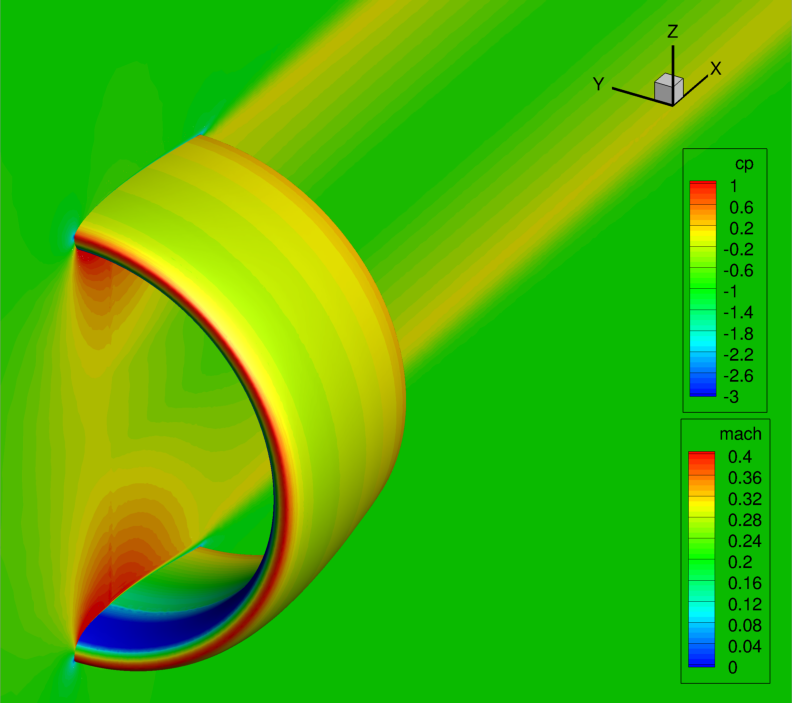
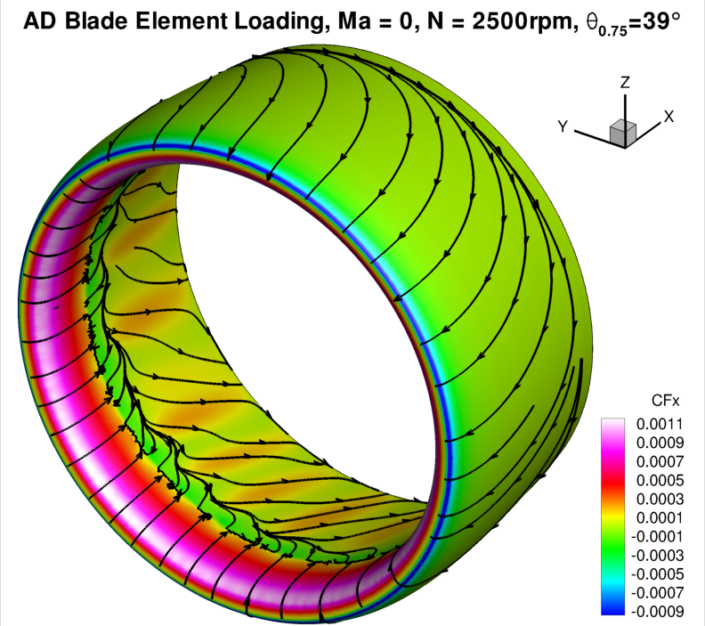
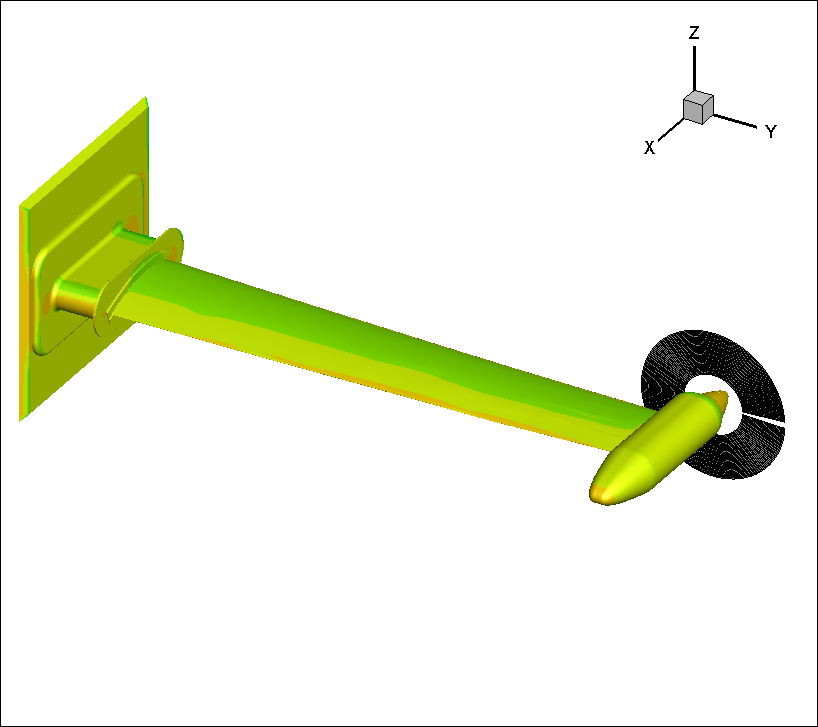
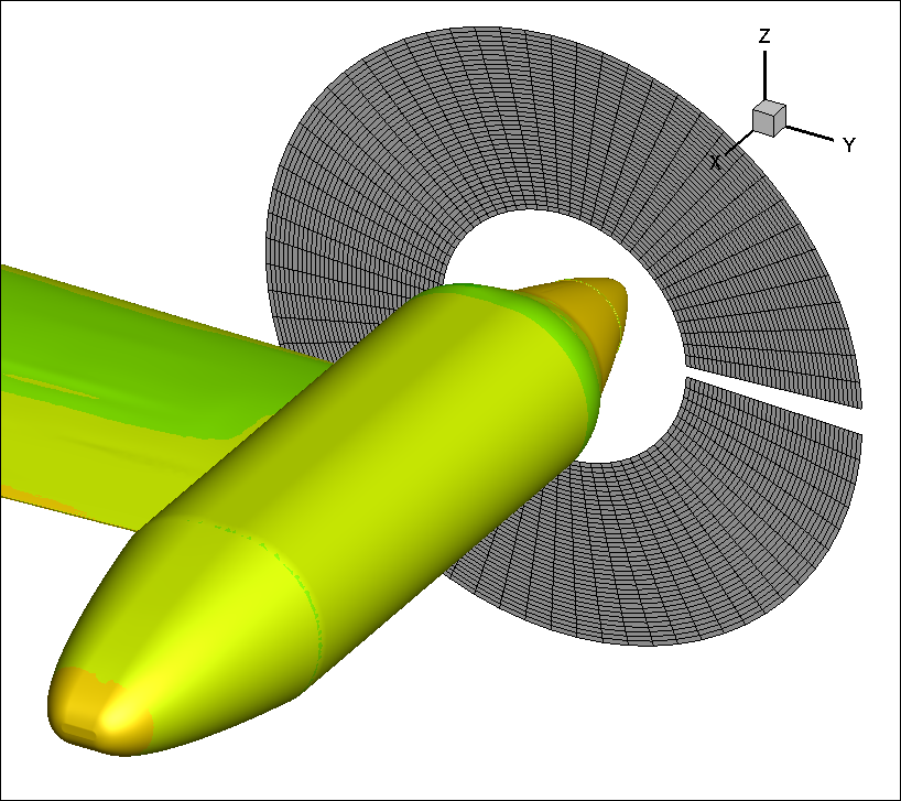
Other Example Cases: NASA Ducted Fan
A NASA ducted fan test case is shown in the figures below. This case was run with the blade-element loading method based on a published blade and nacelle geometry and used as a test case to validate the predicutve ability of this approach for ducted fans.