Input File for Actuator Disk in NSU3D
Actuator Disk
The actuator disk model is a low-fidelity method for analyzing the performance of a propeller or rotor. The propeller or rotor is represented by a disk (without thickness) or a cylinder (with thickness), which is subject to the influence of the blades but allows the flow to pass through the propeller or rotor. Because no physical blade geometry is simulated, the influence of the rotor is enforced by the aerodynamic loading model in the actuator disk method. Therefore, the aerodynamic loading model plays a critical role in the actuator disk method.
Three types of load models are possible:
- Assumed distribution: For a given thrust coefficient C_T and power coefficient C_Q, the loading can be obtained by assuming a prescribed disk load distribution, such as a linear distribution in the radial direction.
- Prescribed loading: The loading is given by other methods or by test data.
- Blade-element theory loading: If the blade geometry is known, the blade-element method can be applied to compute the loading for the actuator disk. The flow velocities combined with the blade geometry and rotational speed can be used to obtain the effective local angle of attack. With the local Mach number and the effective angle of attack, the lift/drag coefficients can be obtained from sectional airfoil CL/CD-AoA-Ma tables or charts and used to prescribe the appropriate momentum source terms.
Enabling Actuator Disk Runs in NSU3D
The actuator disk option is enabled in the NSU3D input parameter file by inserting additional lines after the FORCE/MOMENT COEFFICIENT PARAMETERS and just prior to the MESH DATA FILE specification line. An example is given below as a snippet from the NSU3D input file:
----------------------------------------------------------------------
MACH      Z-ANGLE   Y-ANGLE   RE       RE_LENGTH
0.08      0.        0.00      0.567801e6    12.
----------------------------------------------------------------------
FORCE/MOMENT COEFFICIENT PARAMETERS
REF_AREA  REF_LENGTH XMOMENT  YMOMENT   ZMOMENT  ISPAN
675.6     11.6       2.99     6.35      0.28     2.0
----------------------------------------------------------------------
OPTIONAL ACTUATOR DISK PARAMETERS
IDISK_TYPE IDISK_START IDISK_FREQ IDISK_TRIM IDISK_FM
1.0        0.0         1.0        0.0        0.0
----------------------------------------------------------------------
MESH DATA FILE
../../grids/PWIX_DSV2_AIL0_NP_F_R0p70_FUN3D.part.320
----------------------------------------------------------------------
The additional lines contain 5 parameters to be specified.
- IDISK_TYPE: Set = 1.0 for the current actuator disk model. A setting of 0.0 omits the actuator disk model.
- IDISK_START: Invoke the actuator disk model only after IDISK_START flow cycles have been performed.
- IDISK_FREQ: Evaluate the actuator disk terms only every IDISK_FREQ solver cycles.
- IDISK_ITRIM: Set = 0.0 for standard run. Set = 1.0 for trim run. Note that if no trim targets are specified this will default to a THRUST=0 trim solution.
- IDISK_FM: Set = 0.0 (Obsolete).
Generally the actuator disk can be run from startup and is inexpensive to evaluate, meaning it can be evaluated at each flow solver iteration. Therefore, the usual values for these parameters for a standard actuator disk enabled run are as follows:
- IDISK_TYPE = 1.0
- IDISK_START = 1.0
- IDISK_FREQ = 1.0
- IDISK_ITRIM = 0.0
- IDISK_FM = 0.0
Input/Output Files for Actuator Disk
The files written by the actuator disk code include the following:
- input.actdisk : This is the input file described below. This file is copied from the current run directory to the NSU3D ./WRK directory to facilitate archiving of the inputs with each run.
- actdisk.inputnml.log: The Fortran namelist file uses default values for optional parameters. However, mispelt or missing input parameter names (keywords) will cause the subject parameter to take on the default value. To avoid user confusion, the final values of all input parameters used internally by the actuator disk are recorded to the file actdisk.inputnml.log which is placed in the current run directory.
- actdisk_loads.ncycles.dat : This file logs the source position and loads for each rotor at the end of the simulation. ncycles corresponds to the number of flow solver cycles at which the file is output. The file is written to the ./WRK directory created by NSU3D. This is a TECPLOT formatted file which can be used to verify the placement of the actuator disk sources within the CFD mesh and the computed loads on the disk.
- actdisk_history_rotor.dat : This file logs the history of global forces, moments and thrust/power coefficients (and trim parameters (i.e. collective blade pitch) for trim runs) on each rotor during a run. This is a TECPLOT formatted file and is written to the ./WRK directory created by NSU3D
- Standard Out : Key words in the input.actdisk file can be used to specify output in the NSU3D stdout file (job run file). These include rotor loads and nondimensional thrust and torque coefficients and trim parameters (i.e. collective blade pitch) for trim runs.
Output Units and Dimensionless Coefficients
Although the actuator disk code works with nondimensional quantities internally, input quantities are dimensional and output values are give both in dimensional units and non-dimensional coefficients.
The list of supported dimensional units are given below:
- Angle : rad, deg
- Length : m (meter), cm, mm, km, in (inches), ft, mi, nm
- Mass : kg, g, cg, mg, lbm, slug
- Time : sec, min, hr
- Velocity : m/s, km/hr, ft/s, mi/hr, knot, nm/hr
- Angular Velocity : rad/s, rpm
- Force : N (Newton), lb
- Moment : N*m, m*N, lb*ft, ft*lb
- Power : W (watt), N*m/s, ft*lb/s, lb*ft/s, hp
- Density : kg/m^3, sl/ft^3, lbm/ft^3
- Temperature: K, R
Different definitions for thrust and torque coefficients for rotors can be found in the literature. Here these are defined based on the area of the disk and the tip velocity of the blade as follows:
- Thrust Coefficient: Ct = Thrust / (reference density x (Blade Tip Velocity)^2 x Disk Area) or Ct = Thrust / (reference density x Omega^2 x pi x Disk Radius^4)
- Moment Coefficient: Cq = Moment / (reference density x (Blade Tip Velocity)^2 x Disk Area x Disk Radius)
Input File for Actuator Disk
The actuator disk input file is named input.actdisk and must be present in the NSU3D run directory. This is a Fortran namelist file which contains five distinct namelist types which are listed below. Three of the namelists (actdisk_system, actdisk_rotor, and actdisk_blade) may appear multiple times in a single input file, but the other three may only appear once. The five namelist types are given as:
- actdisk_info : Defines global properties
- actdisk_system : Defines rotor groupings and (optinally) trim properties
- actdisk_rotor : Defines properties of each rotor
- actdisk_blade : Defines properties of each blade type
- actdisk_airfoil : Specifies airfoil tables to be used
In this section all the parameters for each namelist type are described, starting with the required parameters, and followed by the optional parameters.
- actdisk.inputnml.log: The Fortran namelist file uses default values for optional parameters. However, mispelt or missing input parameter names (keywords) will cause the subject parameter to take on the default value. To avoid user confusion, the final values of all input parameters used internally by the actuator disk are recorded to the file actdisk.inputnml.log which is placed in the current run directory.
actdisk_info:
Required parameters
Parameter Type Description nsystem int Number of systems or rotor groupings nrotor int Number of rotors in simulation nblade int Number of unique blade types nairfoil int Number of airfoil tables to be used ref_length real Ratio of the physical length to grid length Optional Parameters:
Parameter Default value Description ref_length_unit "m" Unit associated with ref_length force_output_unit N or lb Units of reported forces in output moment_output_unit N*m or ft*lb Units of reported moments in output ref_density 1.2250 Reference density ref_density_unit kg/m^3 Unit of reference density ref_velocity 287.59754 Reference velocity ref_velocity_unit "m/s" Unit of the reference velocity vel_to_mach 0.8451543 Factor to convert solver velocity to Mach number system_show .false. Flags whether to output system forces at each iteration rotor_show .true. Flags whether to output rotor forces at each iteration implicit_be .false. Flag to compute Jacobians of rotor sources
- Detailed Description:
The required keywords and values must be present in the input file or the module will generate an error message and stop. The first three required inputs (nsystem, nrotor, and **nblade) inform the module how many namelists to look for of each corresponding type. For example, nrotor = 2 instructs the module that it should expect to find two distinct actdisk_rotor namelists in the input file. The number of airfoils (nairfoil) is slightly different in that it provides the dimension for the airfoil array, but there will only be one actdisk_airfoil namelist no matter how many airfoils are specified. The last required value is the reference length parameter (ref_length) that is needed to exchange length data to the flow solver in a consistent manner. The reference length is defined by the formula: ref_length = physical length / grid length. The physical length is any meaningful length (e.g. rotor radius, fuselage length, wing chord, etc.) given in full scale units. The grid length is the dimension of the desired physical length in grid units.
The optional values are given default values within the module and therefore do not need to be entered unless one wishes to change the default value. The default values for this namelist are based on the NSU3D non-dimensionalization, the physical freestream conditions are based on sea-level standard conditions, and the default for all units is the SI system.
ref_length_unit: As stated above, the default value is in meters or "m". Other possible units include inches "in" or feet "ft". A full list of dimensional units available is given below.
force_output_unit and moment_output_unit: These determine the units in which the actuator disk forces and moments are reported in the output. The default values depend on the value of ref_length_unit. If ref_length_unit = "ft" or "in", then the settings force_output_unit ="lb" and moment_output_unit =ft*lb are used. For all other values of ref_length_unit the default SI units are used: force_output_unit**= "N" and **moment_output_unit =N*m**. These can be specified differently in the input file if mixing of SI and imperial units is desired.
Reference Values: The default reference values are taken as sea-level values in SI units. Thus, the default reference density is taken as 1.2250 Kg/m^3. The reference velocity is taken as 287.59754 m/s computed as speed_of_sound/sqrt(gamma), following the NSU3D nondimensionalization. Different values can be input to override the default values and any supported units can be used for each individual input. Consistent unit conversion is handled internally by the code. The default value of vel_to_mach = 0.8451543 is calculated as 1/sqrt(gamma) and corresponds to the non-dimensionalization used in NSU3D. This default should not be changed unless gamma is different than the standard air value of 1.4
system_show and ** rotor_show**: The keywords system_show and rotor_show inform the module what data to output at the end of an iteration. By default system output is off and rotor output is true, since most actuator disk runs will have only one rotor. If multiple rotors are present it is usually recommended that system output also be turned on.
actdisk_system:
Required parameters
Parameter Type Description loadtype int Type of disk loading
Optional Parameters:
Parameter Default value Description system_name "System number" Identification name for this system of rotors center_of_gravity (0.0, 0.0, 0.0) C.G. coordinates for forces and moments cg_unit "m" Units of C.G. coordinates rotor_list (1,2,...) List of rotors belonging to the system (all rotors) target_value
target_value(1:3)
0.0
0.0
Target thrust for assumed load distribution cases
Target System Forces and Moments for Trim Cases
target_id(1:3) FX Identifies Force/Moment Target for Trim Cases target_unit(1:3) "N" Units of target value control_id(1:3) "collective" Parameter for control/trim init_collective 0.0 Initial collective pitch angle of blades (in deg) Detailed Description : Required Parameters:
This namelist defines a system or grouping of rotors. A system of rotors enables recording the aggregate forces and moments of the contributing rotors which can be useful for global control. All included rotors must share the same loadtype, and initial collective values, and the target values apply to the aggregate forces and/or moments of the system. The required keyword (loadtype) and value must be present in the input file or the module will generate an error message and stop.
loadtype specifies the type of disk loading. There are currently 4 principal values:
- loadtype=1 : Constant disk loading
- loadtype=2 : Linearly varying loading (in radial direction)
- loadtype=3 : Blade element loading
- loadtype=4 : User prescribed loading
Assumed loading profiles such as loadtype=1,2 are the simplest for user setup. Therefore, additonal assumed loading profiles are also implemented with the following loadtype values:
- loadtype=21 : Linearly varying loading (same as loadtype=2)
- loadtype=22 : Quadratic loading profile in radial direction
- loadtype=23 : Cubic loading profile in radial direction
The values loadtype =1,2 use prescribed loading profiles as shown in the figures below. The loading extends from the blade root to tip locations, as defined by the first and last chord_sta values in the actdisk_blade namelist. The magnitude of the loading is determined by matching the thrust value specified in the target_value parmeter. Therefore, for loadtype=1,2, the target_value parmeter is required and should be set to the desired thrust of the actuator disk. The resulting power/torque value of the disk, which produces swirl in the wake, is determined by the blade shape and init_collective parameter. In this implementation, the total loading (of which the thrust is a major component) is assumed to be perpendicular to the blade chord at each radial station. Thus, a blade with no twist and init_collective =0 (default corresponding to no blade pitch) will produce 0 torque or Cq. The blade shape is determined in the actdisk_blade namelist primarily using the twist parameters. (Omitting the blade parameters produces a flat blade with constant pitch determined by the init_collective value.) The current formulation produces an approximation to the blade local contribution to overall torque and associated wake effects. Given a blade twist distribution, a target torque/moment/Cq value can be obtained by varying the init_collective parameter. Note that the thrust and moment values produced by the actuator disk are independent of the flow field and can be calibrated with a single iteration of the flow solver prior to the flowfield simulation.
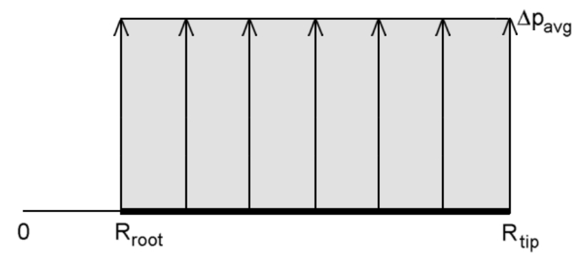
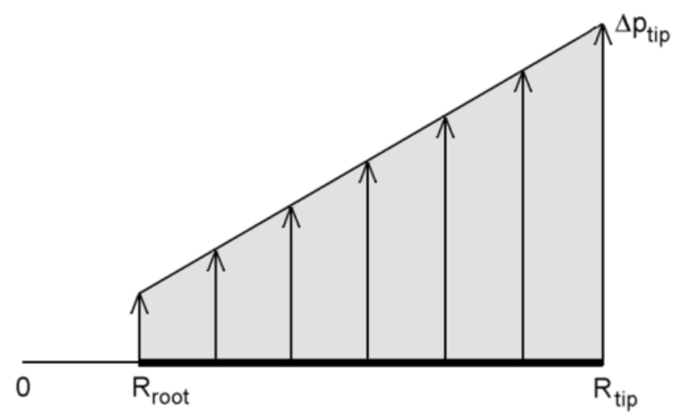
Constant (loadtype=1) and linear (loadtype=2) actuator disk loading profiles
Although different blade loading profiles can be implemented, for more complex loading profiles, the user-prescribed loading option loadtype=4 should be used. Under this option, the user supplies a loading value at each loading station along the radial direction of the actuator disk, as determined by the parameters loading_sta and loading under the actdisk_rotor namelist. These loading values correspond to the total local loading vector. The local direction of the loading vector is assumed to be perpendicular to the chord of the local blade station, as determined primarily by the twist and twist_sta values under the actdisk_blade namelist and the init_collective value. Therefore, the local blade pitch angle, determined by the initial collective and blade twist values, corresponds to the actual total loading direction. For example, if a loading distribution is given in terms of thrust and tangential forces on the disk, the total loading vector must be constructed and the magnitude of this vector is used as the local loading value, whereas the blade twist and collective are specified such that the local blade pitch angle matches the constructued total force vector direction (assumed normal to the local blade chord).
loadtype=3 specifies the blade-element method, where the local loading is deterimed from the local flow conditions and a set of airfoil lookup tables. Note that this method produces actuator disk loading that is dependent on the local flow conditions, whereas the other methods produce constant loading distributions that are independent of changes in the flow field. This setting requires prescribing the blade properties under the actdisk_blade namelist, along with specifying the airfoil table files under the actdisk_airfoil namelist.
- Detailed Description : Optional Parameters:
The optional values are given default values within the module and therefore do not need to be entered unless one wishes to change the default value. The keyword system_name allows the user to provide a more meaningful name to associate with the system rather than particular system. The keyword center_of_gravity expects three real numbers which denote the physical x, y, and z coordinates of the system center of gravity. Note that these coordinates are normalized by the ref_length value and therefore may or may not be the same as the grid x, y, and z coordinates. The point specified for the center of gravity is where forces and moments for the system will be resolved and as a result is also the point where trim targets are applied (if enabled). The keyword rotor_list is only required when there is more than one system, otherwise the default value is to include all rotors. It is important to note that the default value lists rotors in order of appearance.
Optional Parameters for Assumed Load Distributions :
For loadtype=1,2,21,22,23, a load distribution is assumed. The direction of the local load vector is taken as perpendicular to the local blade chord, which results in a local drag compoment which contributes to the rotor torque. The torque and thrust values of the rotor can be prescribed individually as follows:
- target_value: In this case the target value specifies the overall rotor thrust. Note that this parameter should not be specified for prescribed load distribution cases (loadtype=4), since the thrust is obtained by integration of the input loads.
- init_collective: In this case the collective blade pitch angle is constant and set equal to its initial value given by this parameter. Modifying the init_collective pitch parameter results in changes in the rotor torque, which can be matched through user trial and error (noting that rotor performance is independent of the flow solution for assumed load distributions).
For assumed load cases, each rotor should belong to its own system, otherwise the target thrust level cannot be specified individually for each rotor.
- Optional Parameters for Blade-Element Load Distributions : Blade-element load distributions cases (loadtype=3) can be run either with fixed parameters or in trim mode.
Fixed Parameter Cases: This is the default, and is specified by the NSU3D input parameter IDISK_TRIM=0 as described previously. In this case, the init_collective pitch parameter is applied to all rotors that are contained in the actdisk_system and this collective pitch value is held constant throughout the simulation. None of the target parameters or control_id parameters should be specified in such cases.
Trim Cases: To enable a trim case, the NSU3D input parameter should be set to IDISK_TRIM=1.0. Up to 3 target values and control parameters (control_id) can be specified. The number of target and control parameters must be the same. The control parameters include control_id(1:3) = "collective", "lat_cyclic" and "long_cyclic". Lateral cyclic and longitudinal cycle parameters correspond to cyclic pitch controls typical for rotorcraft. For propeller based rotors only the collective pitch parameter is relevant. The target parameters include the 3 force (FX, FY, FZ) and 3 moment (MX, MY, MZ) components computed for the entire system of rotors about the system center of gravity. If target values that cannot be affected by the specific input parameters that are specified, the code will report that the trim operation has failed during the run and continue with default or bounded control values.
The most common trim case consists of matching a specified rotor thrust by adjusting the blade collective pitch angle during the simulation. For this, the init_collective parameter is used to specify an initial guess for the collective angle, which should be close enough to ensure convergence of the trimming model. Setting control_id(1)="collective" instructs the code to use the collective pitch angle to match the target level. Next, the target_id, target_level and target_unit parameters are specified. Here it is important to note that the target forces and moments are those of the system of rotors at the system center of gravity and in the system reference frame (i.e. that of the CFD grid). Thus, to specify each one or more rotor thrusts individually, each rotor must belong to its own unique system. For a rotor with shaft axis aligned with the x-axis, the thrust is set by specifying target_id(1)="FX". If the rotor rotation axis is not aligned with one of the system axis directions, the projection of the thrust into the most relevant system axis direction can be used as the target value. Note also that a negative target_value may be required depending on the direction of the system axis relative to the rotor axis.
An example of a rotor thrust trim case is given in the actuator disk example test cases documentation.
actdisk_rotor:
Required parameters
Parameter Type Description rotation_rate real Angular velocity of rotor shaft_axis 3 reals Direction vector of rotor shaft zero_azimuth_axis 3 reals Direction vector of zero azimuth direction blade_count (int, int,...) Number of blades per blade type Optional Parameters:
Parameter Default value Description rotor_name "Rotor number" Identification name for this rotor rotation_unit "rpm" Units of rotation rate hub_coord (0.,0.,0.) Hub coordinates (i.e. center of rotation) hub_unit "m" Units of hub coordinates nradial 200 Number of sources in radial direction nnormal 720 Number of sources in azimuthal (normal) direction naxis 1 Number of sources in axial direction axis (0., 0.) End points of acuator cylinder in axial direction axis_unit 1 Units of axis values blade_list ( 1 ) List of blade types used by this rotor loading_sta (real,real,...) Radial positions of loading stations (required for loadtype=4) station_unit "m" Units of loadjint stations loading (real,real,...) Loads at prescribed radial stations (required for loadtype=4) loading_unit "Pa" Units of loading values Detailed Description:
This namelist is used to define the properties of each rotor. When nrotor = 1 this namelist should appear only once in the input file, but for nrotor > 1 this namelist will appear nrotor times. Although a system can possess multiple rotors, an individual rotor can only belong to one system. A rotor definition will typically only have one blade type, but here is generalized so that it can have multiple blade types (for example in order to model a rotor with a damaged blade).
The required keywords and values must be present in the input file or the module will generate an error message and stop. The keyword rotation_rate not only specifies the rate of rotation, but also the direction of rotation. A positive value indicates that the rotor spins counter-clockwise when viewed from above and a negative value indicates the rotor spins clockwise from above. Note that, while the rotatio_rate is important for the blade-element loading (loadtype**=3) for the other prescribed loadings it is still required although only for normalizing the reported thrust and moment coefficients, and will not affect the computed flow field.
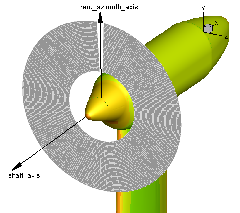
The keyword shaft_axis is used to define the direction of positive thrust, as well as the rotation vector of the rotorto which applies the rotation_rate. The keyword zero_azimuth_axis defines the general direction of the psi=0 location for cyclic pitching parameters. An illustration of this axis is provided in the figure below. Technically, zero_azimuth_axis is irrelevent for propeller simulations, where no cyclic variations are assumed. Both of these axes are unit vectors, but the module automatically normalizes any vector provided. In addition, the module will adjust the zero azimuth axis such that it is perpendicular to the shaft axis, so it is not necessary to be exactly perpendicular when defining it.
The keyword blade_count is used to define how many blades are present for each type. For simplicity, 99% of rotors have identical blades within the tolerance of minor imperfections, so in most situations the blade count will be equal to the number of rotor blades. For some unique rotors and situations, it may be desirable to define more than one type of blade for a rotor. If this is the case, then blade count will be an array that will list how many blades of each type are present. For example in order to model a four bladed rotor that has sustained some damage affecting the aerodynamics of one blade, one could define a standard blade and a damaged blade and set blade_count(1:2) = 3, 1.
The keyword rotor_name allows the user to provide a more meaningful name to associate with the rotor. The keyword hub_coord expects three real numbers which denote the physical x, y, z coordinates of the rotor center of rotation. hub_coord is normalized by ref_length, so the values may or may not be equal to the hub coordinates specified in grid units. The point specified for the hub coordinates is where forces and moments for the rotor will be resolved.
The keyword blade_list is closely associated with blade_count. For a single rotor problem, the keyword blade_list will typically be omitted and will default to blade_list=1. When more than one rotor is present or when multiple blade types are present, the user will have to specify which blade index to apply. Blades are indexed by order of appearance in the input file. In situations where more than one blade type is listed, the module will use the blade with the longest radius to compute the rotor coefficients.
The keywords nradius, nnormal and naxis define the number of momentum sources in each direction of the actuator disk or cylinder. The default values (200, 720, 1) have been found to produce good results and naxis=1 specifies an actuator disk with zero thickness. Spreading the loading over an axial distance using naxis>1 corresponds to the use of an actuator cylinder. In this case, two values for axis(1:2) must be specified to determine the axial extent of the actuator cylinder. The momentum sources are positioned uniformily in the actuator disk/cylinder and positioned in the CFD mesh, where their values are interpolated onto the nearest CFD mesh points. The actuator disk extends from the blade root to tip locations, as defined by the first and last chord_sta values in the actdisk_blade namelist. An illistration of the source locations for an actuator disk is given in the figure below.
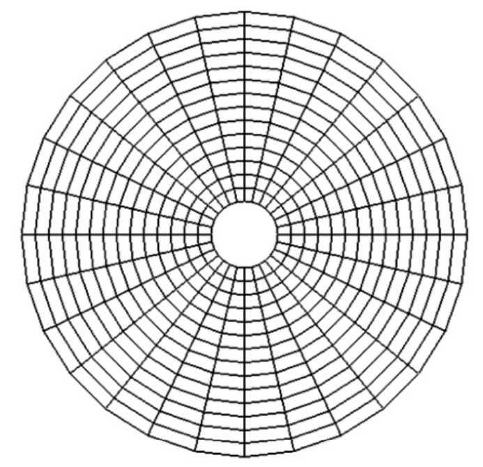
Actuator disk with grid of source locations extending from blade root to blade tip
- Prescribed loading parameters : The keywords loading and loading_sta are required when user specified loading is employed, corresponding to the setting loadtype=4 in the actdisk_system namelist. In this case, a set of loading stations must be prescribed along with the corresponding loads at each station. The default units for the loads and stations are SI units (Pascal for loads, meters for stations). The stations correspond to radial locations along the blade, between the root and tip, and the loads are assumed to be in the direction normal to the local blade chord, as described above in the actdisk_systyem section. These loading values correspond to the total local loading vector. The local direction of the loading vector is assumed to be perpendicular to the chord of the local blade station, as determined primarily by the twist and twist_sta values under the actdisk_blade namelist and the init_collective value. Therefore, the local blade pitch angle, determined by the initial collective and blade twist values, corresponds to the actual total loading direction. For example, if a loading distribution is given in terms of thrust and tangential forces on the disk, the total loading vector must be constructed and the magnitude of this vector is used as the local loading value, whereas the blade twist and collective are specified such that the local blade pitch angle matches the constructued total force vector direction.
actdisk_blade:
Required parameters
Parameter Type Description chord (real, real, ...) Blade chord length values chord_sta (real, real, ...) Radial positions of chord values airfoil (int, int, ...) Airfoil ID table (only required for loadtype=3) Optional Parameters:
Parameter Default value Description blade_name "Blade number" Identification name for this Blade station_unit "m" Units applied to unspecified *_sta_units keywords chord_unit "m" Units associated with the chord length chord_sta_unit (station_unit) Units associated with chord table stations airfoil_sta (chord_sta) Radial positions of the airfoil table airfoil_sta_unit (station_unit) Units associated with airfoil table stations twist (0.,0.,...) Blade twist table twist_sta (chord_sta) Radial positions in the twist table twist_unit "deg" Units associated with twist twist_sta_unit (station_unit) Units associated with twist table stations sweep (0.,0.,...) Blade sweep table sweep_sta (chord_sta) Radial positions in the sweep table sweep_unit "deg" Units associated with sweep sweep_sta_unit (station_unit) Units associated with sweep table stations offset (0.,0.,...) Blade offset table offset_sta (chord_sta) Radial positions in the offset table offset_unit "m" Units associated with offset offset_sta_unit (station_unit) Units associated with offset table stations Detailed Description:
This namelist is used to define the properties of each blade. When nblade = 1 this namelist should appear only once in the input file, but for nblade > 1 this namelist will appear nblade times. Blades can be shared by more than one rotor and rotors can possess more than one blade type. This namelist consists entirely of blade property tables.
The required keywords and values must be present in the input file or the module will generate an error message and stop. The minimum input required to define a blade in the module is a list of radial stations (chord_sta), the chord length at those stations (chord). Additionally, for the blade-element method (i.e. loadtype=3), the airfoil keyword must be used to specify the airfoils used at each station. For specified load cases (i.e. loadtype=1,2,4) the blade planform is not needed. However, the first and last blade stations are used to determine the extent of the actuator disk as shown in the figure above, and therefore at least 2 stations must always be included.
The optional keyword "blade_name" can be used to identify each blade in the place of the default blade numbering.
Blade properties are entered through the use of five tables: chord, airfoil, twist, sweep, and offset. Four of the tables are entered through the use of four keywords: the variable value (tablename), the radial station to apply the variable value (tablename_sta), the units of the variable value (tablename_unit), and the units for the radial station (tablename_sta_unit). The only exception is the airfoil table, which uses indices for the keyword airfoil and therefore does not have a keyword airfoil_unit.
The station variables (tablename_sta) for airfoil, twist, sweep, and offset are optional. If these tables are not present then the station values are assumed to be the same as the values found in chord_sta. The keyword station_unit allows the user to specify the units for all tablename_sta_unit keywords with a single input. It is also acceptable to use the station_unit keyword, but individually set specific tables to be something different.
The keyword twist is used to define any twist that may be present along the span of the blade. More specifically it represents a difference in the pitch of a specific section of the blade with the reference pitch of the blade. A positive value of twist indicates that the local station will have a larger pitch setting than the reference station. The final local pitch value for the blade station is given by the station pitch plus the collective angle, which corresponds to the init_collective value in the actdisk_system namelist when no control law is being used (and can vary dynamically with the application of a control law or trim). If no twist values are specified, a flat blade with no twist is assumed.
The keyword sweep is used to define any sweep that may be present along the span of the blade. A positive value of sweep indicates that the local station is rotated aft of the reference blade line. The keyword offset is used to define the chord-wise position of the aerodynamic center. A positive value of offset indicates that the local station reference point is forward of the blade reference line. An important item to know about sweep and offset is that they do not affect the location of the source terms passed to the flow solver. Sweep affects which components of flow velocity are used to compute the angle of attack and offset influences the computation of the velocity components due to blade motion. In general, sweep and offset will only be used to model a swept tip blade.
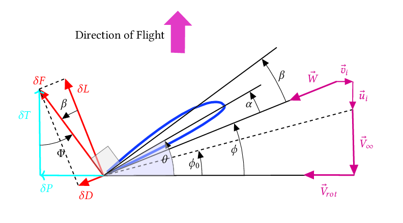
For prescribed loading cases (loadtype=1,2,4) the only parameters that are relevant are: chord, chord_sta, twist and twist_sta. As mentioned previously, the twist angle has a different meaning and purpose for blade-element runs versus prescribed loading cases as shown in the figure below. For loadtype=3 blade-element cases, the twist angle is the blade installed angle, shown as theta - theta_0 in the figure, where theta_0 is the initial collective angle. For other loading types, the twist angle is the total force angle, shown as phi+beta in the figure.
actdisk_airfoil:
Required parameters
Parameter Type Description airfoil_file ("char","char",...) C81 Airfoil Table File Names Detailed Description:
This namelist provides a list of all airfoil files to be read by the module. The airfoil file namelist appears only once no matter how many airfoils are specified by nairfoil. The keyword, nairfoil, defined in actdisk_info defines the dimension of the array airfoil file defined in this namelist.
This namelist has only one keyword, airfoil_file, which is a one-dimensional array that lists the names of all of the airfoil table files to be read by the module. The index values of this array are referenced by the keyword, airfoil, in the actdisk_blade namelist. This namelist is separate from the blade definition namelist to enable airfoil tables to be reused by different blade definitions. Path names should be acceptable as long as the character string is shorter than 256 characters long. To keep track of the index assigned to each airfoil table, it is recommended that each file be listed on a separate line:
Airfoil table data is currently read using the C81 format. Additional details on writing a C81 formatted airfoil table are provided in the Appendix under Airfoil Table Format.
APPENDIX: C81 Airfoil Table Format
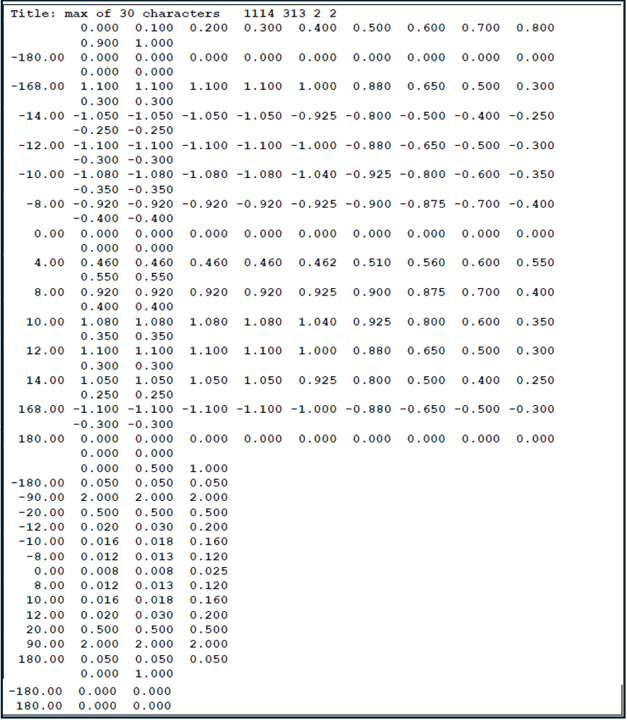
Airfoil properties are entered using the C81 airfoil table format. This table format is divided into four sections: header, lift coefficient table, drag coefficient table, and pitching moment coefficient table. The header consists of a title and a numeric sequence that defines the dimensions of the three tables. The tables are organized such that the rows represent the airfoil properties at a constant angle of attack (alpha) and the columns represent the airfoil properties at a constant Mach number (M). If the (alpha, M) combination falls outside of the table range, the airfoil properties are set equal to the closest table values.
A simple table is shown below which highlights some of the styles associated with this particular format. The first line of the file is the header line, which contains a 30-character title and six 2-character numbers that specify the table dimensions. When viewing a file in this format it is important to understand that this is a fixed-format file, which means that each item is read from an expected number of characters. In the example below the sequence (1114 313 2 2) looks like it is a four number sequence consisting of 1114, 313, 2, and 2; however, this is actually a series of six numbers consisting of two characters each. Therefore, the correct number sequence is 11, 14, 3, 13, 2, and 2. This sequence listed in order is:
- number of Mach values in the CL table
- number of angle-of-attack values in the CL table
- number of Mach values in the CD table
- number of angle-of-attack values in the CD table
- number of Mach values in the CM table
- number of angle-of-attack values in the CM table
The second line is the Mach numbers used to define the lift coefficient table. Whenever the table has more than nine Mach values, the remaining values will continue on the line below. This is true for all multiples of nine, so a table with 20 Mach values will have values one through nine on line one, values ten through eighteen on line two, and values nineteen and twenty on line three. The Mach values are always indented seven spaces. After the Mach values are listed, the rows of the table begin starting with the angle of attack followed by up to nine lift coefficients. Similar to the Mach values listed in the column headings, only nine lift coefficients can appear on each line. Continuation lines are indented seven spaces and may contain up to nine more values before another continuation line must be started. After a lift coefficient has been entered for each Mach number at a particular angle of attack, the next set of angle-of-attack data can be entered, continuing until the lift table is complete.
After the lift table is completed, the drag table is entered in an identical format as the lift table. Finally, the moment table is entered after the drag table is complete. The Actuator Disk code does not currently use the pitching moment coefficient table, but this table must present for the airfoil file to be read correctly. If pitching moment data is not known, a dummy two by two table can be entered as shown in the sample file. A final comment on the airfoil tables is the numbers do not need to contain spaces as shown below. Each value of the table is assumed to be 7 characters long, so the value 10.00001.015521.23761 would be read as 10.0000, 1.01552, and 1.23761.